


 thickness control Face exclusion to create “open” solids Full Parametrics support Not supported Spline faces (fillet, sweep, skin, spline segments in curve based…")

 and sab (binary) file formats Allows bi-directional exchange of solids, surface and wireframe Currently the most reliable solids data exchange format Transfers geometry only No feature or histor…")


, conics (104), copious data (106) Surface Untrimmed (118, 120, 122, 128) Trimmed (144) Solid Solid BREP (186, 514, 510, 508, 504, 502,)")
, conics (104) Solid/surface Decomposed to precise wireframe BREP Decomposed to surface collection (trimmed or untrimmed - 128, 142, 144) Text Hid…")


 + (3 * load_2)")
 Surfaces -- quad dominant or all trias Volumes -- tets only Map meshing for surfaces and volumes 3/4 side surfaces, 5/6 face volumes Composite edge support")


 Stress Displacement Strain Strain energy Reaction force")


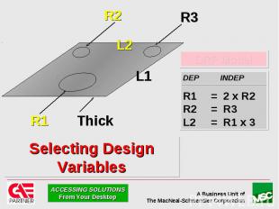
 By Modifying Design Variables")

 Shell thickness, non-structural mass Design sensitivity Effect of a change in a design variable on Design Objective, Design Constraint(s) Shape and siz…")


 Maintain design intent (Attach DRP model(s) to solids i…")

/ variable(s) against design cycle Display geometry at intermediate design cycles Review results of final design in FE_Results Standard resul…")


 p-order min/max control Recommended p-order range 3-10 Adaptivity automatically turns off below specified von Mises stress or strain minimum Turns off adaptivity …")

 mesh refinement supported for automeshed p-elements Uses ERROR DATASET calculated from FER TOOLKIT error estimation")


 kinematic systems i.e. the motion of the system is completely constrained by applied mot…")
 Add constant, harmonic, step, random motion Add motion constraints (e.g. cams), applied forces, springs, gravity Solve")


 Recommend >= Pentium 75MHz, 32Mb RAM 125 Mb swap space Any Microsoft supported graphics adapter in 256 color mode WindowsNT Windows 3.1 and Windows95 not available Licensing Node-lock, st…")


 Checking clearance/interference Housing/r…")
Презентация на тему: Презентация по сопромату3


Geometry Geometry FE Analysis Optimization

Geometry Full function ACIS based modeler Constraints full partial none ACIS data exchange AutoCAD Bentley Integraph HP

Geometry Modify dimensions

Geometry Parametric relationships

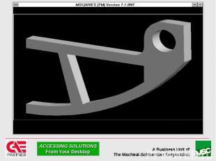
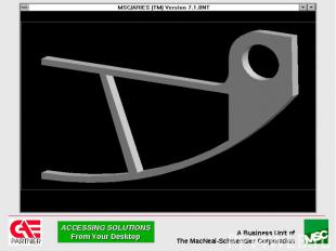
Geometry Complex solids Skin operator Sweep operator Extensive blending and chamfering Region operator to sub-divide geometry Map meshing Load footprint areas Symmetry

MSC/ARIES Base - Assemblies Visualization Packaging Clearance Interference Mass properties

MSC/ARIES Base - Mass Properties

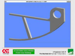
Geometry - Regioning

Geometry - Regioning

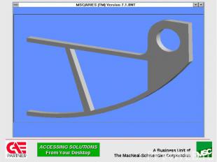
Geometry - Regioning

Geometry - Regioning

Pre Release Solids Shelling Shelling of solids to thin walled solids Per face (uniform) thickness control Face exclusion to create “open” solids Full Parametrics support Not supported Spline faces (fillet, sweep, skin, spline segments in curve based primitives, extrude with draft <arc segment>)
 and sab (binary) file for")
Geometry Interface - ACIS Support for ACIS sat (ASCII) and sab (binary) file formats Allows bi-directional exchange of solids, surface and wireframe Currently the most reliable solids data exchange format Transfers geometry only No feature or history information

Geometry Interface - Autocad Import

Geometry Interface - Autocad Import

Geometry Interface - Autocad Import

Geometry Interface - Autocad Export

Geometry Interface - IGES Import Supports Wireframe Point, line, arc, composite curve, spline (112,126), conics (104), copious data (106) Surface Untrimmed (118, 120, 122, 128) Trimmed (144) Solid Solid BREP (186, 514, 510, 508, 504, 502,)

Geometry Interface - IGES Export Supports Wireframe Point, line, arc, composite curve, spline (112,126), conics (104) Solid/surface Decomposed to precise wireframe BREP Decomposed to surface collection (trimmed or untrimmed - 128, 142, 144) Text Hidden line removal Silhouette edge generation

Geometry Interface - DXF Import Wireframe Point, line, arc, polyline Text

Geometry Interface - DXF Export Supports Wireframe Point, line, arc, composite curve, spline Solid/surface Decomposed to precise wireframe BREP Text Hidden line removal Silhouette edge generation

Geometry Interfaces - STEP, VDAFS PDES/STEP AP203 Import and export of solid/surface/wireframe data VDAFS Import and export of surface/wireframe data Data format that emphasizes surface transfer Used predominantly by European automotive industry

Geometry Interfaces -Stereolithography Translates solids into standard “stl” format Rapid manufacture for physical part prototyping

Geometry Geometry FE Analysis Optimization

Load and Boundary Conditions LBC’s applied to geometry or to nodes & elements Supported loads Force, moment, pressure Gravity Velocity Translational Rotational Acceleration Translational

Load and Boundary Conditions Constant or functional varying magnitude Geometry based load and boundary conditions survive geometry change

Load and Boundary Conditions Direction control for load/boundary conditions XYZ Radial Tangential
 + (3 * load_2)")
Load and Boundary Conditions Load case combination (5 * load_1) + (3 * load_2)

FE Meshing Automeshing technology Edges -- 1D elements (beam, gap, rigid, spring) Surfaces -- quad dominant or all trias Volumes -- tets only Map meshing for surfaces and volumes 3/4 side surfaces, 5/6 face volumes Composite edge support

Auto Meshing

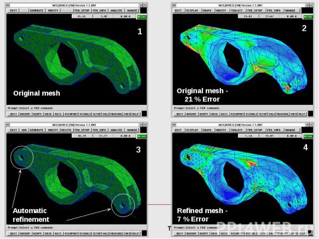
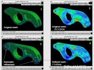
FE Meshing Adaptive mesh refinement Automatic mesh refinement to optimize mesh density Use with automatically generated h or p meshes Global or local refinement New mesh density based on current error versus target error Reduces mesh density related errors

FE Meshing

Results Review Display options Vector Contour Graph Animation Cutting plane Results in any coordinate system Data averaging control Results combination Error calculation

Linear Statics Loads constant with time Material assumed linear and perfectly elastic Results calculated Stress Displacement Strain Strain energy Reaction force

Normal Modes Calculates undamped natural modes of vibration Material assumed linear and perfectly elastic Results calculated (normalized) Stress Displacement Strain Strain energy Reaction force

Linear Buckling Calculates load factor for critical buckling Material assumed linear and perfectly elastic Results calculated Stress Displacement Strain Strain energy Reaction force

Non-Linear Statics Geometric non-linearity Change in stiffness associated with large deformations Load follows deformed shape Material non-linearity Bi-linear elastic/plastic with plastic strain, or Non-linear elastic, no plastic strain Compressive/tensile stress-strain curves can be different

Non-Linear Statics

Structures-2 Non-Linear Statics Load Following

Linear Transient Dynamics Time varying geometry and finite element loads Structural and modal damping Results calculated for each time step Stress Displacement Strain Velocity Acceleration Reaction force

Heat Transfer Steady state and transient linear and non-linear heat transfer Heat transfer modes Conduction Free convection Forced convection Radiation Temperature and time dependent Heat flux Mass flow rate

Heat Transfer

MSC/ARIES To MSC/PATRAN

MSC/ARIES To MSC/PATRAN

Geometry Geometry FE Analysis Optimization

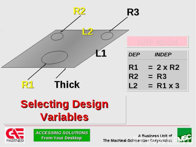
Optimization An Automated Process That: Satisfies Your Design Objective Within Design Constraint(s) By Modifying Design Variables

Optimization - Overview 1 Design Objective minimize/maximize weight, frequency, load factor ‘n’ Design Constraints - local and or global min/max stress, displacement, freq, load factor ‘n’ Design Variables Dimensional variables Element shell thickness, Non Structural Mass Solve multiple constraints simultaneously Linear statics (with multiple load cases) Modal (per mode shape max/min control) Buckling analysis

Optimization - Overview Shape Geometry dimensions as design variables Sizing (element properties) Shell thickness, non-structural mass Design sensitivity Effect of a change in a design variable on Design Objective, Design Constraint(s) Shape and sizing can be combined


Optimization - Application Build solid or surface geometry Associate dimension variables in Parametrics: Use as design variables for Optimization Maintain design intent (Parameterize using DRP) Maintain design intent (Attach DRP model(s) to solids in Parametrics)

Optimization - Application Create finite element model Select Optimization application 1 Design Objective minimize/maximize: weight, frequency, load_factor ‘n’ Design Constraints - local and/or global min/max stress, disp, freq, load factor ‘n’ Design Variables Dimensional, Shell thickness, Non Structural Mass

Optimization - Results Review Post process in Optimization application Graph design objective/ constraint(s)/ variable(s) against design cycle Display geometry at intermediate design cycles Review results of final design in FE_Results Standard results review process Animate between FEmodels across design cycles

P-Elements - Overview Automatically increases element’s shape function polynomial order during solution until convergence Convergence based on per element strain energy difference between p-order changes Mesh remains unchanged

P-Elements - Overview Each edge of each element has its p-order independently controlled in MSC/NASTRAN

P-Elements - Application Supported element types Tetrahedron Brick Pentahedron (wedge) p-order min/max control Recommended p-order range 3-10 Adaptivity automatically turns off below specified von Mises stress or strain minimum Turns off adaptivity for elements where stress and or strain is negligible Reduces CPU time and system resources

P-Elements - Application Can mix h and p elements Use p-elements in areas where high accuracy required, h-elements elsewhere

P-Elements - Application Hex to tet mesh connection works identically for p-elements: Automatic (h-adaptive) mesh refinement supported for automeshed p-elements Uses ERROR DATASET calculated from FER TOOLKIT error estimation

P-Elements - Results Review p-element results review identical to h-elements Can display final p element order contours

Geometry Geometry FE Analysis Optimization

Mechanisms Two- and three-dimensional mechanism modeling analysis and results review Uses MDI/ADAMS Kinematics solver Solves motion of fully constrained (0 DOF) kinematic systems i.e. the motion of the system is completely constrained by applied motion(s) and joint constraints

Mechanisms Pre Processing Create link geometry Geometry can be solid, surface or wireframe Add joints (supports all MDI/ADAMS joints) Add constant, harmonic, step, random motion Add motion constraints (e.g. cams), applied forces, springs, gravity Solve

Mechanisms Results Review Animated motion of links Motion path of any point Joint reaction force/moment Rotational/translational link displacement, velocity, acceleration Clearance/interference between links Results interrogation in local static/dynamic coordinate system

Geometry Geometry FE Analysis Optimization

Plastics 3D mold fill analysis Uses Moldflow/Flowcheck solver Solves “Will It Fill” Fast analysis to calculate areas of fill / no-fill / possible fill Experiment with number of injection points/ location, material and part thickness Solves “Fill_Pattern” Fill time Air trap location Weld line locations

Plastics

Plastics

Modular Configuration

Modular Configuration

MSC/ARIES Base

Optional Modules

Platform Support
 Recommend >= Penti")
Platform Requirements - WinNT Intel based (not Digital NT) Recommend >= Pentium 75MHz, 32Mb RAM 125 Mb swap space Any Microsoft supported graphics adapter in 256 color mode WindowsNT Windows 3.1 and Windows95 not available Licensing Node-lock, standalone only No network license support Requires Ethernet adapter for licensing

Platform Requirements - Unix Supported Unix workstation 32Mb RAM 125 Mb swap space Licensing Node-lock, and Floating network license

Geometry Geometry FE Analysis Optimization

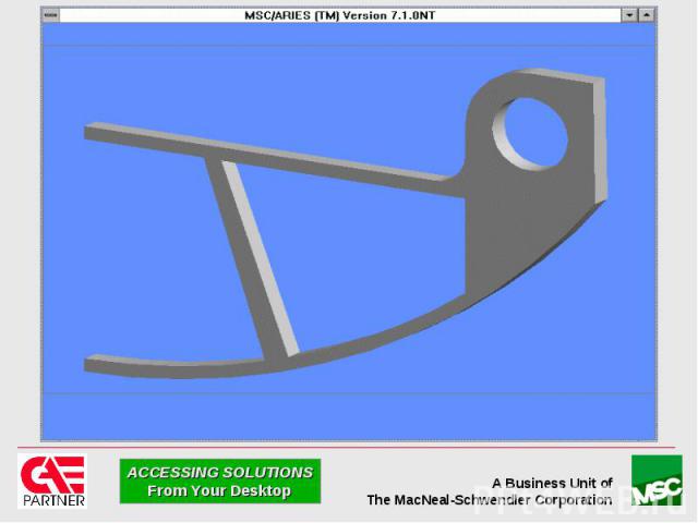
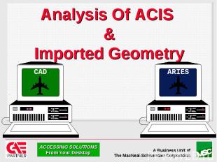
MSC/ARIES Positioning Standalone Design and Analysis System Designed and analyzed in MSC/ARIES Analysis of ACIS Based Geometry Design built in CAD system Design geometry import into MSC/ARIES Analyzed in MSC/ARIES Focus on Ease-of-Use and Automation For...

MSC/ARIES Positioning Structural Thermal Mechanisms Plastic Molding Analysis

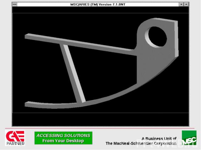
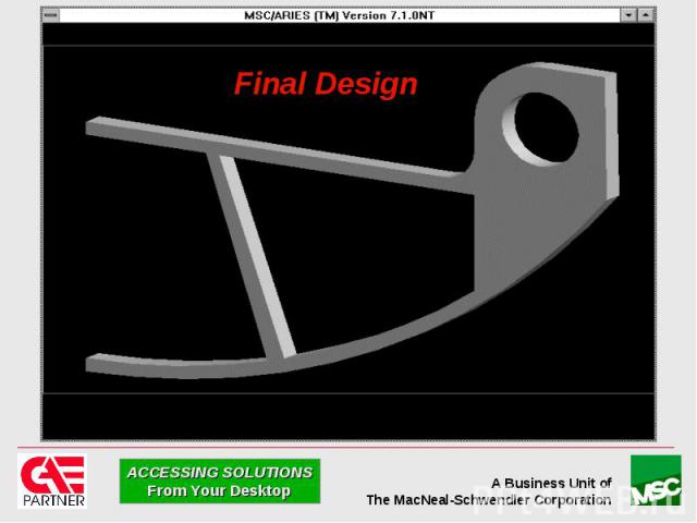
MSC/ARIES The Flow of Development

Positioning of MSC/ARIES

Positioning of MSC/ARIES

Positioning of MSC/ARIES

Positioning of MSC/ARIES

THE END

Mentor BoardStation Interface Bi-directional interface using Mentor IDF 2.0 file format Imports Mentor Board Station PCB and component data as an assembly of solids Components represented by automatically generated primitives or user created representations

Mentor BoardStation Interface Supports board holes, vias, keep out and keep within areas 2D curves can be added to represent additional keep outs, keep within etc. Applications Analysis (e.g. modal, thermal) Checking clearance/interference Housing/rack design

 числа на несколько единиц")


